AutoCAD 2010 introduced a great new feature, parametric constraints. You can constraint objects in two ways:
- Geometrically: You can constrain objects to meet at a point, be horizontal, be vertical, be perpendicular, be concentric, and more
- Dimensionally: You can constrain the dimensions of objects. For example, a you can constraint a line to be 4 units long, or two lines to be 4 units apart.
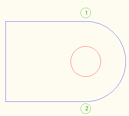
This tutorial, adapted from my book, AutoCAD 2010 & AutoCAD LT 2010 Bible, takes you through the process of constraining the simple model you see here. The goal is to constraint the objects so that all you can do is stretch the model, keeping the relationships the same. However, you want the circle’s diameter to remain unchanged, because it represents a hole for a fixed-size axle.

Parametric constraints in AutoCAD
- Starting at Point 1, draw a horizontal line to the left, 4 units long.
- Continue to draw a line segment vertically down, 4 units long.
- Continue to draw a line segment horizontally to the right, 4 units long. End the LINE command.
- Start the ARC command. At the Specify start point of arc or [Center]: prompt, select the endpoint at Point 2.
- At the Specify second point of arc or [Center/End]: prompt, choose the End option. Then choose the endpoint at Point 1.
- At the Specify center point of arc or [Angle/Direction/Radius]: prompt, press Shift + right-click to open the OSNAP shortcut menu. Choose Mid Between 2 Points. then choose the endpoint at Point 1 and the endpoint at Point 2.
- Start the CIRCLE command. At the prompt for the center, specify the center object snap of the arc. Set the radius to 0.75 units.
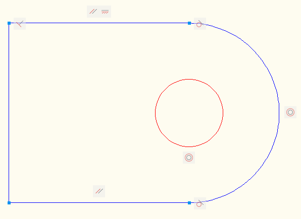
- Click the Parametric tab in AutoCAD 2010. Choose AutoConstrain in the Geometric panel.
Notice that AutoCAD adds the following constraints:
- Perpendicular
- Parallel
- Horizontal
- Tangent
- Concentric
- Coincident

Geometric constraints in AutoCAD
You can see which constraint is which by hovering your cursor over a constraint icon; a tooltip appears with the name of the constraint. Coincident constraints don’t display an icon at first, so put your cursor over the small blue square until the icon appears; then move your cursor over the icon to see the tooltip.

Parametric constraints in AutoCAD
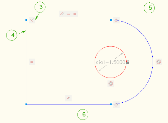
- To constrain the three lines to be of equal length, click the Equal button in the Geometric panel of the Parametric tab. Then pick at Point 3 and Point 4 in the model above. Because of the other constraints, you don’t need to constraint the bottom horizontal line.
- To fix the circle’s diameter, in the Dimensional panel, click the Diameter button. Select the circle and specify a location for the dimension line as prompted. Press Enter to end the command.
- Start the SCALE command and select all the objects in the model. Using the lower-left corner endpoint as the basepoint and 1.5 as the scale factor. The model just moves!! That’s because you’ve constrained the size of the circle.
- Undo the SCALE operation.
- Repeat the SCALE command. Select all the objects in the model, but this time, press Shift and select the circle to deselect it. Now try the same scaling operation. This time it works.
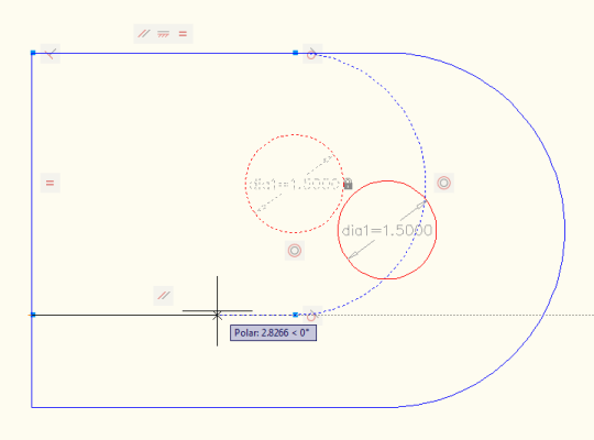
- Now start the STRETCH command. Specify a crossing window (from right to left) from Point 5 to Point 6 in the above model. and again use the lower-left corner as the base point. Drag to the right. Notice that you can’t elongate the model, because the 3 lines are constrained to be equal. You can only scale the model, which is just what you want. The circle stays the same size.

Stretching the model with parametric constraints in AutoCAD 2010
- Combine or subtract 2D shapes to create custom shapes - February 17, 2022
- Working with linetype scales - January 18, 2022
- Rename named objects–blocks, dimension styles, layers, and more - December 21, 2021

 Instagram
 LinkedIn
 Facebook
Hi Ellen,
As usual, I enjoy reading your comments and tips. I have one comment regarding how you constructed the radius on this part. A WAY easier method is to draw the three lines as indicated, but then issue the Fillet command and pick each end of the lines (not by the vertical line). Doing so will fillet the two lines with an arc that has the same diameter as the distance the two lines are apart. It doesn’t matter what Fillet radius is set to, ACAD “knows” that you’re trying to put a radius at the end of those two lines and constructs it for you.
Keep up the great work
Bob
Bob,
That’s a great tip!
Thanks,
Ellen
Great tip, but note this doesn’t work on polylines. Drove me crazy trying to figure out why I couldn’t get this tip to work until I tried it with regular lines.
Is there any way of making this happen: Constraint Parameter 1(A):6, Constraint Parameter 2(B):4 and Constraint Parameter 3:A-B with a min of 4?
Nice Tutorials by the way.
Have a nice day.