 This is a guest post by Khwaja Ibrahim. He is a Mechanical Engineer by profession and a CAD Engineer from Pakistan. His services range from designing for 3D Printing, Sheet Metal, Injection Molding and Manufacturing processes to providing Photo-Realistic Rendered Images.
He gets the utmost satisfaction in bringing ideas to life allowing him to demonstrate his creativity, designing and imaginative skills. As you can see, he also writes tutorials. This one is from 12CAD.com
By default design, AutoCAD’s line is a single entity. This singularity of the line allows it to be treated as a simple drawing element without the leverage of more complex types. However, for those of you who may require such a feature, there is a way other than grouping different colored lines into one.
As said, by default the line is a simple element hence to replicate functionality not built-in, we need to setup the proper environment before we proceed with the actual development. See the below screenshots for a step by step explanation of the prerequisites of sawing multicolored lines.
Preparation
Step 1: Command: MLSTYLE. Use the command MLSTYLE to access the Multi-Style menu. When you press enter, the dialogue box should open up.
Step 2: View current profiles
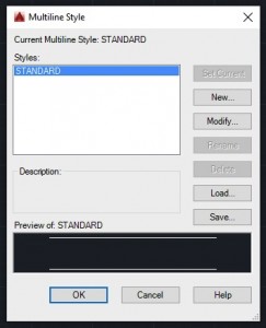
By default a “Standard” profile is defined for regular line drawing. This is also set to the current profile in selection. At any time, this one profile will be available if there are no other. Create a new profile as shown below.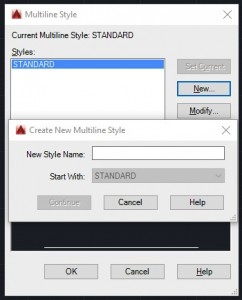 Step 3: Create a new Multi-Style profile
Give your profile a name and press continue for the configuration menu.
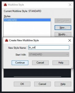
Step 4: Set up your profile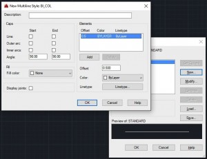
The name that you entered is on the top of the current screen. That’s your profile configuration screen where you can define your style.
- Caps – For a multi-colored line, we’re going to select the Line option for Start & End. The angle doesn’t matter for now. Experiment with it on your own when you want the line to start/end with an arc.
- Fill – This is the background color. If this is set to none, then where you assign the line to inherit the color from the layer, the line will be drawn transparent. There are two functions here, we’ll cover both later.
- Display joints – Whether to display the joints where the intervention is defined.
- Elements – Just as on your canvas, the elements section refers to the elements you will be drawing when using this style. The properties are shown below.
- For multi-colored lines, the offset should be kept to 0 for all elements defined. This is because the offset is vertical in nature and displaces the lines from each other placing them upon one another. Add another element with the properties as shown below.
- Color – Self explanatory
- Line type –
 Define the kind of line you want this element (segment of the final line) to be.
Note: We’re using the dashed line type for both elements. The line types can be loaded in the case you don’t see them when you click on the “Line type” button.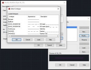
Load line types if you can’t see the ones you need by clicking on load and selecting from the list as shown below.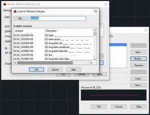
Using the Dashed line type we set up both lines to contain dashes within them. Here the two features of the Fill option come into play.
As can be seen below, the first element’s color is inherited from the layer. Which basically means that one Magenta colored line with dashes will have yellow behind it because that’s the base layer. This can be left to colorless so you can have a line that alternates between opaque and transparent after the same interval.
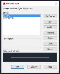 Now the preview shows a white line because the element on top is taking its color from the layer which previews as a white line.
Step 5: Set the new profile as current.
Click the Set Current button. And then click OK. (see below)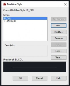
With that, you’ve prepared your default environment for some workaround-fashioned multi-colored lines. Let’s draw!
Drawing
Step 1: Draw the line
The line needs to be drawn using the MLINE command. 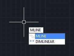
This selects the line tool with the current multistyle profile. Now draw the line. This is pretty basic, but just to rid everyone of confusion, the colors will only show once the drawing is committed. So don’t be disheartened if you don’t see two hues after the first click. (See below).
First click –
![]()
Second click –
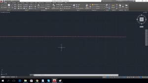
Zoomed in –
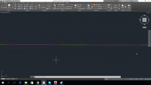
If interested in more tutorials, check out these AutoCAD exercises.
Do you have another way to create multi-colored lines? Leave a comment!
- Combine or subtract 2D shapes to create custom shapes - February 17, 2022
- Working with linetype scales - January 18, 2022
- Rename named objects–blocks, dimension styles, layers, and more - December 21, 2021

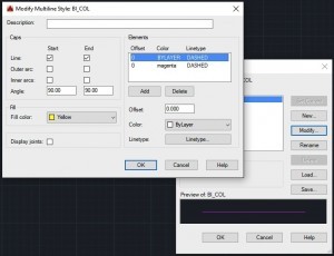 Define the kind of line you want this element (segment of the final line) to be.
 Instagram
 LinkedIn
 Facebook
you van draw a continous line in one color and and interrupted line {hidden, center etc} on top of this line for the second color
in fact you can use as many colors as you can fit into the spaces
we control it with
LINE COLOURS AND PEN WIDTH FOR B&W DWC:,
AutoCAD colour template numbers Colour Pen WidtBolour Prinlinar–
1
I 0
2 Yellow 0.50 $ $ (!J
zS2
3 Green 0.24 0 w zw w 0 r=
4 Cyan 0.23
<( 0 w :::J(9<(
_J w 0:: _J -(90co co (9
5 Blue 0.15 000000 00
‘r'” C\I(‘I’) LO c.o 0CX) 0)
6 Magenta 0.20 I’-,
+J +J +J +J
+J +J +J +J +J
7 White/ Black 0.35 ‘r'”‘r'”‘r'”‘r'”‘r'”‘r'”‘r'”‘r'”‘r'”
8 Gray Gray 0.15
0’r'”C\I(‘I’) LO c.o I’-,CX)
9 –
10 –
9 0.10
1.00
242 242 Border of Dvvg .8 Black
th ctb files I like to share with every one but unable to attach the file
Thanks for this Tutorial
Excellent and intelligently written post … this will help me out of the funk I’ve found myself in lately .. thanks!
Nice article.It is very useful for me.
Thanks for sharing.
Wow this was really helpful. Lorenx from lagos nigeria
I worked with AutoCAD electrical mainly drawing schematics of the components we built. Many times multi-conductor cables were used that had wires with 2 colors (main color & a tracer). I’d create 2 layers, one being the main color the other the tracer. The main layer was a solid line and the tracer was a dashed line. Then it was simply a matter of copying the main color wire and changing it’s layer to the tracer, then attaching the two at one end so they were overlayed making sure the tracer was on top.