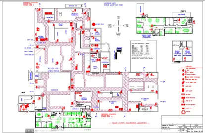
Ralph, a subscriber to my AutoCAD Tips Newsletter, sent me a drawing that he called “an embarrassment.” He wouldn’t explain the details of why he thought it was so bad, but wanted some advice about how to fix drawings that have been revised over many years.
Old system variables
Some of the issues could be related to old system variables. For example, in this drawing, DIMASSOC is set to 1, which creates non-associative dimensions. That means that when the dimensions objects are edited, the dimensions don’t update automatically. AutoCAD has offered associative dimensions since Release 2002, but if the drawing was created before then, you’ll see non-associative dimensions.
You should fix this by changing the value of DIMASSOC to 2 and then using DIMREASSOCIATE to associate the dimensions to their objects. I explain this process in my post, “Dimensions and associativity.”
Objects not set to ByLayer
You may find objects that are not set to ByLayer and want to fix them. The easiest way to do that for the entire drawing is to use the SETBYLAYER command. At the Select objects: prompt, type All and press Enter. Then follow the prompts for ByBlock and blocks.
Warning: This may change your drawing a lot if you have many objects that aren’t set to ByLayer. For example, in this drawing, fire extinguishers were on the Safety Equipment layer, which had a black color. But they had all been set to have a red color. You might want to simply change the color of that layer. Or you might find that you need to change the layer of many objects.
I have a tip that goes into the SETBYLAYER options more in detail–“Maintain standards by returning objects to ByLayer settings.”
Text and dimensions on multiple layers and styles
Remember the ROMANS, ROMAND, and SIMPLEX text styles? Older drawings still use them. Over the years, text styles may have changed, but older text probably wasn’t updated. The same is true of dimension styles. Text and dimensions may be on various layers, as well. For example, most of the text in this drawing is on the TEXT layer, but there’s a section of text that’s on a layer called TRIVIA.
Finding all of the exceptions can be tricky. One way is to create a Standards file and test the drawing against it. That will be the topic of a future tip, but for now, I’ll discuss some less automated techniques.
You can use the QSELECT command to find objects that meet certain criteria. I have a post on the topic, “Use Quick Select to select objects in your AutoCAD drawing.” (It includes a video tutorial, so check it out!)
For example, you can find text that is set to a specific color. Then, you can isolate that text, meaning that you hide everything else. This process helps you find the objects that you need to fix.
Here is a section of the drawing.
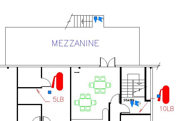
Let’s say that most of the Mtext is on ROMANS. I might want to find text that uses another text style. I would type qselect on the command line and complete the dialog box like this:
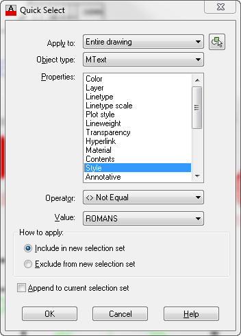
After clicking OK, Mtext objects that don’t use the ROMANS text style would be selected.
Then, I would use the Isolate feature. To do so, right-click and choose Isolate, Isolate Objects, as you see here.
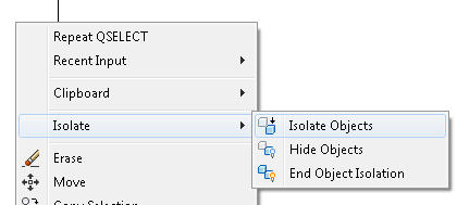
Here’s the result in the drawing—a couple of words that don’t use the ROMANS text style. When I select them and look in the Properties palette, I see that one uses the Standard style and the other uses the ROMAND style. Since they’re selected and isolated, it’s easy for me to use the Properties palette to change their style to ROMANS.

There are lots of other possible drawing problems–title blocks on the Model tab instead of on a Layout tab, hatches using the wrong scale–the list could go on and on.
Have you had to bring old drawings into shape? What techniques did you use? Please leave a comment so others can benefit from your experience!
- Combine or subtract 2D shapes to create custom shapes - February 17, 2022
- Working with linetype scales - January 18, 2022
- Rename named objects–blocks, dimension styles, layers, and more - December 21, 2021

 Instagram
 LinkedIn
 Facebook
Some of my favorite commands for cleaning up drawings;
Select Similar
Flatten
Layer Merge
Also, a couple of LISP routines that remove formatting that was done in the MText editor and another to change any attributes to text that were left from an attributed block that was exploded. (These can be very troublesome in XREFs.)
Thanks for your suggestions! Would you care to share the AutoLISP programs?
I think the first thing I would do is copy and paste “all” objects in this drawing into a current prototype drawing of the same scale which has all the current dimstyles, text styles etc. set up to current standards (use PASTEORIG which pastes to original coordinates). Then you can begin making sure all the text is one acceptable style, color, height, width etc. Same thing with the dimensions. Change them to your current dimstyles. You may even have to re-create a dimension here or there if the text has been dragged around to odd positions over the life of the drawing.
I did not write the LISP routines so I won’t post them directly but a search of http://www.theswamp.org or http://www.cadtutor.net for STPMText and TAG2TEXT will get them for you.
Copy paste is a great idea and if PS MS was used I would try to keep that format so you do not have to worry about scaling issues later. Also I would consider using a dark gray for the existing drawing and the new addition with color. As stated above I would create a standard for all dems and leader lines and also use the same font color and height on all drawings. Those are just what I see from a glance. Also try to clean the legend up a little and if there is several drawings in the once project use the same clean legend you created.
Good tips, Ellen!
Definitely SelectSimilar. Tweak the Settings for more control over what gets selected.
Like Wallace said, copy/pasteorig is a great way to get started from a known environment that has you standards predefined. One catch is you’ll loose any Paper Space tabs in the “messy” drawing. Using “ALL” is the quickest way, but it can select objects that you may not want to copy, like empty text strings, empty block definitions, etc. If you choose to select objects by a window (rather than by “ALL”), make sure all the layers are turned on, thawed and unlocked, annotation visibility is on, and all “frames” (wipeouts, XClip, Images) are on.
I’ve found LayerWalk to be very handy for “dissecting” drawings. Granted, it’s not an edit tool, but can be very revealing. Also, LayTran (Layer Translater) is extremely useful if you need to clean up (merge, delete) layers. If you are cleaning up multiple drawings, the tranlation “maps” can be shared via export & import.
Lastly, for cleaning up MText, StripMtext (http://cadabyss.wordpress.com/2010/01/04/stripmtext-v5-0/) is awesome.
Chris, thanks for all of those ideas!
And I’ve never heard of StripMtext–it sounds useful. Like Ctrl+Shift+Z in MS Word (strips formatting).
Concurring with this article and not wanting to change a word I would like to share a new command SBL created for use in AutoCAD 2008 written in Autolisp.
Since some users have a need to have all properties to be set bylayer and the number of mouse clicks would be overwhelming, I developed SBL.LSP creating new command SBL. SBL changes all objects properties in model and layouts to bylayer. It uses command “setbylayer”, not found prior to AutoCAD 2007, using the select “ALL” option with a “setbylayermode” of 127 (AutoCAD 2008 initial setting). Depending on your release of AutoCAD you may find it necessary to increase this setting for the initial setting will be larger moving to newer releases (ACAD2008 = 127 – ACAD2012 = 255).
To find the Initial Value of “setbylayermode” type “setbylayermode” press Enter then hit the F1 key. Then change it in the code to get all properties.
All this being said, on execution, SBL saves system variable settings before setting new values. It uses tilemode to move to MS and PS. It uses (layoutlist) to work through each layout. When all is said and done SBL restores system variables to the saved preset condition.
How to load: copy the code below to notepad and save as SBL.LSP. Place it in a folder location like C:\temp. Add this path in Option/File/Search path. To load type (load “SBL”) and press Enter. To RUN type SBL. As always, it is wise to save your drawing before running any new code. It is also wise to set a return to mark using UNDO and option M just in case results are not what you expected. Using UNDO option B returns to the marked point undoing everything back to that mark.
SBL.lsp is a very basic Autolisp. Most everything I addressed can be added to this code like adding condition statement checking the release of AutoCAD and then setting system variable “setbylayermode” to that value.
If you decided to improve this code please repost on this site so we may all keep sharing.
;;;;;;;;;;;;;;;;;;;;;;;;;;;;;;;;;;;;;;;;;;;;;;;;;;;;;;;;;;;;;;;;;;;;;;;;;;;;;;;;;
;;; Program: SBL.LSP
;;;
;;; Created 03/11/2013 for a Banjo Picker friend
;;; Created BY: Tommy Holder
;;;
;;; Set by layer (SBL) takes the present condition
;;; properties of objects and sets them to bylayer
;;; in Model and each layout
;;;
;;; Feel free to modify to suit your needs
;;;
(defun c:sbl (/ oldslm oldtile)
(setq oldtile (getvar “tilemode”))
(setvar “tilemode” 1)
(setq oldslm (getvar “SETBYLAYERMODE”))
(command “_.setbylayermode” 127)
(command “_.SETBYLAYER” “all” “” “y” “y”)
(setvar “tilemode” 0)
(foreach n (layoutlist)
(command “_.layout” “S” n)
(command “_.SETBYLAYER” “all” “” “y” “y”)
)
(setvar “SETBYLAYERMODE” oldslm)
(setvar “tilemode” oldtile)
);end c:sbl
(princ “\nType SBL and press Enter to RUN”)(princ)
;;;;;;;;;;;;;;;;;;;;;;;;;;;;;;;;;;;;;;; end of SBL
v/r
Tommy
Thanks, Tommy! I uploaded that file so people can download it. It’s zipped at https://allaboutcad.com/wp-content/uploads/2013/03/setby.zip
Ellen
Thanks Ellen and Tommy!
This is exactly the type of issue i wish to address, but I have two variants of the problem for which I think there MAY be a simple solution.
My equipment is based on assemblies of assemblies of assemblies of assemblies… all gathered from the manufacturer’s or created by CAD people that are in a hurry. That leads to blocks within blocks within blocks… all having their own layers of unique names. (Interior colors solved thanks to “SBL”)
My techniques has been to require that ALL elements within a block be on layer 0, but some elements are customized (linetyoe, color…) to uniform style.
Visibility param helps to manage this (centerlines, dimensions being hidden for general display). Heavy use of LAYWALK to check drawings. Layers are used to collect systems (“LOOPS”)
Problem 1:
Changing the layer is easy IF you can select it. QSELECT and even selecting a single block does NOT give you access to the layers inside interior blocks. the only solution has been to “peel the onion”, redefining the blocks to eliminate interior layers. Way too time consuming, since blocks come in faster than they can be cleaned up.
Is there a simple command that will allow me to select the elements of all layers INSIDE interior blocks.
Even a lisp routine that would allow be to select all elements of a certain layer to change them to a different layer would be helpful.
Problem 2:
Note that due to the use of MInsert, even exploding the blocks isn’t always an option to “get at” the elements.
Good piece of Info. Thanks Ellen
Sunith Babu L
Great post Ellen
QSelect was one of the first Autocad commands I learnt on my own and one of my most used.
The QSELECT feature is great for cleaning up drawings but its also a great ‘inventory’ tool. I use this feature to instruct users how to find out how many objects (ie Blocks) exist in a busy drawing.