Measuring angles can be challenging. Sometimes, two lines that create an angle don’t even intersect or intersect, but not at their endpoints. For this reason, specifying an accurate vertex for the angle is important.
To dimension an angle, start the DIMANGULAR command. You can get there in two ways:
- Home tab> Annotation panel> Dimension drop-down list> Angular
- Annotate tab> Dimensions panel> Dmension drop-down list> Angular
You see the Select arc, circle, line, or <specify vertex>: prompt. You can respond in one of 4 ways:
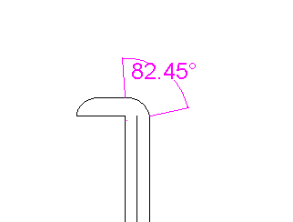
Select an arc
If you select an arc, DIMANGULAR dimensions the arc. The arc’s center is the vertex of the angle. You can place the dimension either inside or outside the arc.
Select a circle
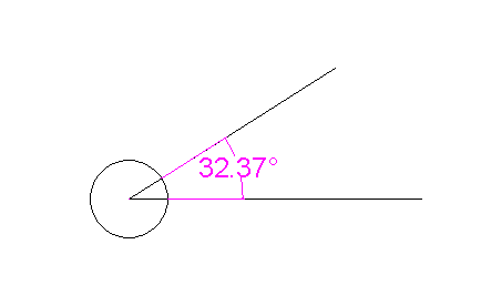
If you select a circle, DIMANGULAR uses the point you picked when selecting the circle as the first angle endpoint. The circle’s center is the vertex. You are prompted for the second angle endpoint; pick a point on the circle. In this way, you are dimensioning an arc, which is just a portion of a circle.
Tip: Let’s say that you draw a circle and then draw lines that cross the circle, as you see below. If you want to select the circle and try using the Intersection object snap, you end up selecting a line, because it’s on top of the circle. That’s because newer objects are on top of older objects. If you want to selecft the circle, select it, and right-click it, and choose Draw Order> Bring to Front. Of course, you could get the same angle measurement by selecting the lines, but if you want to be dimensioning the circle (perhaps you’ll erase the lines later), bringing the circle to the front can help.
Select a line
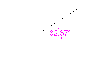
If you select a line, DIMANGULAR’s prompt asks you for a second line. If the lines don’t intersect, the implied intersection is the vertex.
Press Enter to specify all the points of the angle
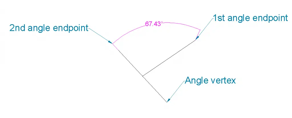
If you want to individually specify the vertex and the two angle endpoints, just press Enter. You’re then prompted for the vertex, 1st angle endpoint and 2nd angle endpoint.
Dimensioning the outside angle
In the above example, the dimension measures the minor angle, the portion that is less than 180°. By simple moving the cursor below the vertex, you can measure the major angle, as you see here.
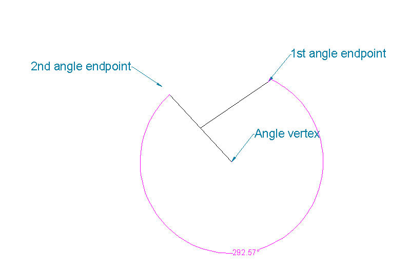
Always use object snaps when specify the vertex and the angle endpoints. This will ensure that you get an accurate measurement.
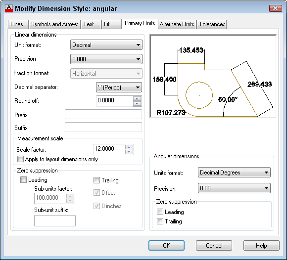
Remember that you can specify the decimal precision of a dimension in the dimension style. For angular dimensions, start the DIMSTYLE command to open the Dimension Style dialog box. Then, on the Primary Units, tab, use the Angular Dimension section’s Precision drop-down list.
Do you have any tips for dimensions angles? Leave a comment!
- Combine or subtract 2D shapes to create custom shapes - February 17, 2022
- Working with linetype scales - January 18, 2022
- Rename named objects–blocks, dimension styles, layers, and more - December 21, 2021

 Instagram
 LinkedIn
 Facebook

thanks for the information